FREQUENTLY ASKED QUESTIONS (FAQ)
If you do not find an answer to your question below please call 800 527-2726 or click on Contact us page.
BRAKE ASSEMBLIES
- What is keeping my brakes from rotating freely?
- Why do my brakes not stop the aircraft effectively?
- Why do my brake linings display uneven wear?
- What causes my brakes to squeal?
BRAKE DISCS
- How can I tell if I have Cleveland or McCauley wheel and brake assemblies?
- How do I determine the proper brake disc part number for my aircraft?
- Why are brake disc minimum wear specifications important and where can I find them?
- What is brake disc heat checking?
- What causes a brake disc to warp?
- What causes the brake pedal to pulsate?
- How do I break in new brake discs ?
BRAKE LININGS
- How can I tell if I have Cleveland or McCauley wheel and brake assemblies?
- How do I determine the proper brake lining part number for my aircraft?
- What is the minimum allowable thickness of a worn brake lining?
- What is it the minimum wear indicator on RAPCO brake lining and how does it work?
- What causes damage or cracking to organic brake linings?
- What causes uneven wear on brake linings?
- Organic vs Metallic aircraft brake linings, how do I determine the difference?
- How are Organic or Metallic linings removed or installed?
- When two different Linings PN’s are required on the same brake assembly, which goes where?
- How do I break in new brake linings?
- What is the difference between the Cessna 208 Caravan standard and upgraded brake linings?
BRAKE RIVETS & MOUNTING PINS
- How do I use the RAPCO rivet tool?
- Can a brake rivet have any splits in the flare?
- How are metallic linings removed or installed?
- What tool do I use to install mounting pins?
- What rivet tool do I use when replacing wear pads on Cleveland heavy brake assemblies?
BRAKE SHIM INSULATORS
DE-ICE BRUSHES and WIRE HARNESSES for Propeller
EXHAUST GASKETS
FUEL PUMPS
- What causes premature failure of fuel pumps?
- What does the NV mean in some of the Dukes fuel pump part numbers?
- What does the RX mean at the end of some of the dukes fuel pump part numbers for Cessna?
- What is the difference between the Dukes Fuel Pump part numbers 4140-00-17 and 4140-00-17N?
DRY AIR PUMPS & PNEUMATICS
- Why does my Dry Air Pump rattle when I hold it in my hand and shake it?
- Why can I not turn my Dry Air Pump drive spline with my fingers while holding it in my hand?
- How do I check the vane wear on RAPCO brand dry air pumps?
- What is the replacement service time or hours in service for a dry air pump?
- Why does the lifespan of a dry air pump seem to differ from one aircraft to another?
- What factors cause the premature failure of a dry air pump?
- Why am I getting a shorter life out of my dry air pumps after installing a digital display?
- Can I buy a kit to overhaul my own dry air pump?
- When do I need to install a 211CC-9 overhaul or RAP215CC-9 new dry air pump?
- What are the differences between new and overhauled exchange dry air pumps?
- What is the difference between the 200 series, 240 series, and 400 series dry air pumps?
- Does it matter in which direction I mount my pump?
- What is the torque spec for the mounting nuts on dry air pumps?
SUCTION GAUGE
VACUUM REGULATORS
BRAKE ASSEMBLIES
What is keeping my brakes from rotating freely?
Why do my brakes not stop the aircraft effectively?
Why do my brake linings display uneven wear?
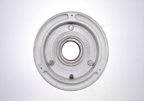
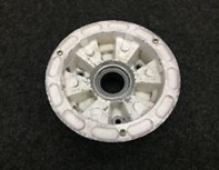
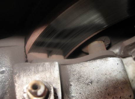
The conditions listed above are often the result of a history of over torqued back plate tie bolts. Aircraft brake cylinders are cast out of relatively soft magnesium or aluminum. It is very important to follow the proper torque spec for each specific brake assembly. If the tie bolts are over torqued, they can draw the back plate into the cylinder causing permanent damage. Because there is less material toward the inner edge of the mounting surface where the bolts are located, it can easily crush the cylinder casting changing the angle of the mounting surface (See Figure 1). Due to the arm of the back plate and lining and the angle of the damaged cylinder face, the inner edge of a new brake lining can now force constant pressure against the brake disc making it very difficult for the wheel to rotate freely. At the same time with only a small area of the linings surface contacting the brake disc there is less ability for the assembly to stop the aircraft, at least until the lining wears flat. (See Figure 2) The increased localized pressure can create excessive heat, damaging the brake disc and or linings. The above conditions can result in a hazardous situation and should be corrected immediately. To check for this, clean and inspect the brake cylinder back plate mounting surface for a depression, not to exceed 0.005 inch. (0.127mm) (See Figure 1). If this condition exists, replace the brake cylinder and tie bolts. See Cleveland Maintenance Manual appendix A3. It is important to use a calibrated torque wrench along with the proper torque specification for each brake assembly part number. See your Aircraft Maintenance Manual for proper specifications and instructions. Torque Spec PDF.
Dragging or binding of brake assemblies can be the result of debris between the pistons, cylinders, and O-rings. In addition, worn or corroded anchor bolts and torque plate bushings can also cause problems. All these items should be cleaned, inspected, and replaced if necessary. Be sure to consult your Aircraft Maintenance Manual.
Pilot technique can be another potential cause of brake problems. In some cases, a pilot might not even be aware that they have a habit of riding the brakes and over-temping them. It can simply be the angle at which their foot contacts the control pedal that can create a problem. Taxing while riding the brakes can cause the brake discs to over-temp creating hot spots and warping the discs. This can result in a pulsation or vibration.

Figure 1.

Figure 2.

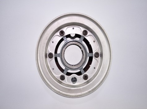
Figure 3.
What causes my brakes to squeal?
We do not necessarily hear the high frequency vibrations produced in the braking process. However, when components in the brake assemblies become worn or loose, it can increase the vibration resulting in the noise you hear. Carefully inspect linings, rivets, mounting pins, pressure plates, back plates, guide pins and torque plate bushings for fit, wear or damage. Also check brake disc for condition and minimum wear dimensions.
BRAKE DISC
How can I tell if I have Cleveland or McCauley wheel and brake assemblies?
To determine if you have a Cleveland or McCauley wheel and brake assemblies first look in your Aircraft Parts Manual. To visually determine, look at the wheels on the main landing gear. Cleveland wheels are solid and have a dish like appearance. McCauley wheels have a six spoke appearance. They are primarily used on Cessna and Reims Cessna single engine aircraft from the early 1970s through the early 1980s. In addition, they were also used on Bellanca, Fuji, Light Plane Components and Lake Aircraft. McCauley original equipment part numbers started with a B-30…, C-30…, or a D-30… Cessna had their own part numbers for the McCauley wheel assemblies, they started with C16300…
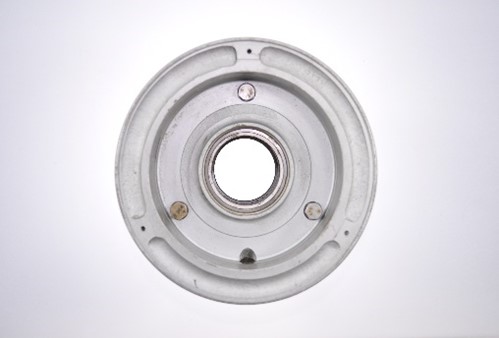
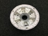
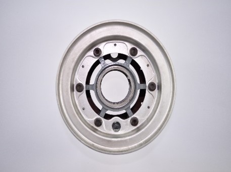
| Cleveland | McCauley | McCauley |
How do I determine the proper brake disc part number for my aircraft?
First determine if you have Cleveland or McCauley wheel and brake assemblies as explained above. Look in your Aircraft Parts Manual when selecting a part for installation. The RAPCO Inc. Brake Application Guide PDF might also be of some help. Cleveland wheel and brake assemblies are most commonly used on single engine aircraft, however in the case of Cessna single engine aircraft that were manufactured from the early 1970s through the early 1980s, it is important to first determine if your aircraft is equipped with McCauley brakes instead. If you do have McCauley assemblies be sure to look in the application guide under your aircraft model where it says “with McCauley Brakes”. Also, you will find two additional McCauley references in the back of the Application Guide. Section 5: McCauley Brake Disc Cross Reference and Comparison Guides. Section 6: McCauley Brake Disc Dimensional Guide. It is recommended that you compare the dimensions listed with that of your current McCauley brake disc.
A few of the Cessna 150s and 172s use McCauley wheel assembly PN: D30063. The brake disk has six - ¼” bolt holes. McCauley PN: B-30007, Cleveland PN: 164-30007 or Cessna PN: C163002-0101. This particular part is not manufactured by RAPCO Inc. however you should be able to find it in a web search.
Why are brake disc minimum wear specifications important and where can I find them?
Brake discs that are worn below minimum wear limits no longer have the mass required to properly absorb the kinetic energy while stopping. They tend to overheat and will rapidly wear both the disc and
linings. Also, the brake piston O-rings get so close to the lip of the cylinder that they can leak brake fluid and let air into the system leading to a spongy brake pedal or brake failure. If discs are at or below minimum wear they must be replaced. In addition, if a disc surface is coned or warped more than 0.015” of an inch or 0.381 mm, the disc must be replaced.
Minimum wear specifications for Brake Discs or Linings can be found in the Cross Reference with Minimum Wear PDF guide by clicking the link on Brake Disc or Brake Linings pages of the RAPCO website.
What is brake disc heat checking?
Heat checking is represented by tiny cracks that start at the outer edge of the brake disc wear surface and run inward towards the center. It is usually caused by rapid expansion on the surface of the metal due to overheating. In addition, discs that are worn below minimum wear limits no longer have the required mass to properly absorb the kinetic energy for a given aircraft and will more readily overheat causing this condition. Minimum wear specifications can be found in the RAPCO Brake Cross Reference with Minimum Wear PDF Thickness Specifications. If discs are at or below minimum wear, they must be replaced.
What causes a brake disc to warp?
Coning is a condition in which the wear surfaces of the brake disc become warped and are no longer parallel to the mounting flange. This can occur when the brake disc becomes overheated as in the case of a rejected takeoff or especially when a brake assembly has been damaged and no longer applies even pressure to both sides of the brake disc. This damage often results when the back plate bolts have been over torqued. If the disc surface is coned more than 0.015 inch (0.381 mm), the disc should be replaced. In addition, discs that are worn below the minimum wear limits no longer have the required mass to properly absorb the kinetic energy and will more readily overheat causing this condition. Minimum wear thickness specifications can be found in your aircraft maintenance manual or also in RAPCO Inc. Brake Cross Reference with Minimum Wear PDF If discs are at or below the minimum wear limit, they must be replaced.
What causes the brake pedal to pulsate?
This condition can occur when the disc has been worn to its minimum wear thickness and develops hot spots and or becomes warped. At this point the disc must be replaced. See Product Guide or Cross Reference with Minimum Wear PDF for minimum wear specifications.
It can also be the result of brake discs that have been over temped due to excessive braking from short stops, rejected take offs or prolonged use as in riding the brakes during taxiing. Also from the binding of the caliper due to over torqued back plate bolts, dirty cylinders and O-rings or damaged anchor pins.
How do I break in new brake discs?
Please click on link for RAPCO Inc. Service Letter RASL-004 PDF for brake disc and linings break in procedures.
BRAKE LININGS
How can I tell if I have Cleveland or McCauley wheel and brake assemblies?
To determine if you have a Cleveland or McCauley wheel and brake assemblies, first look in your Aircraft Parts Manual. To visually determine look at the wheels on the main landing gear. Cleveland wheels are solid and have a dish like appearance. McCauley wheels have a six spoke appearance. They are primarily used on Cessna and Reims Cessna single engine aircraft from the early 1970s through the early 1980s. In addition, McCauley wheels were also used on Bellanca, Fuji, Light Plane Components and Lake Aircraft. The original equipment McCauley part numbers started with a B-30…, C-30…, or a D-30… Cessna had their own part numbers for the McCauley wheel assemblies that started with C16300…
| Cleveland Wheel | McCauley Wheel | McCauley Wheel |
How do I determine the proper brake lining part number for my aircraft?
First determine if you have Cleveland or McCauley wheel and brake assemblies as described above. Look in your Aircraft Parts Manual when selecting a part for installation. The RAPCO Inc. Brake Application Guide PDF might also be of some help. Cleveland wheel and brake assemblies are most commonly used on single engine aircraft, however in the case of Cessna single engine aircraft that were manufactured from the early 1970s through the early 1980s it is important to first determine if your aircraft is equipped with McCauley brakes instead. If you do have McCauley assemblies be sure to look under your aircraft model where it says, “with McCauley Brakes”. All McCauley brake assemblies require the PN: RA066-30026 Linings. CAUTION do not use the -105 lining on McCauley brake assemblies. They look very similar however the rivet hole alignment is off by ½ of the width of a rivet. Using the wrong lining will cause stress and can crack the lining. Along with the proper McCauley Lining PN: RA066-30026 the Rivet PN:RA105-00200 is required.
What is the minimum allowable thickness of a worn brake lining?
Minimum wear thickness for organic or metallic linings is 0.100 inch (2.54 mm) thick, except for the part numbers RA066-09100 and RA066-09200. For each of these two linings the minimum wear thickness of the sintered lining material by itself should not exceed 0.030 inch (0.76mm).
What is it the minimum wear indicator on RAPCO brake lining and how does it work?
Most RAPCO Inc. organic linings have a Minimum Wear Indicator built into them. It is a small notch located on each end of the lining. At the point where the notch is no longer visible, the lining has reached its maximum wear and only 0.100” of an inch of material remains. When the notch is near this point or no longer visible the lining should be replaced. Continuing past this point can result in reduced braking performance and cause damage to the brake disc.
What causes damage or cracking to organic brake linings?
In the repeated process of removing and replacing brake linings, the back plates and or pressure plates of a brake assembly can develop a lip or mound of metal around the rivet hole. This lip can cause the organic lining material to crack. Destruction can occur during the riveting process or also when brake pedal pressure is applied. It is important that the lining have full contact against the back plates and pressure plates. The back plates and pressure plates and back plates should always be deburred, wire brushed and inspected for flatness before installing replacement linings.
An impact or hammer type rivet tools can especially cause stress risers in the organic lining material. It can also cause damage to the back plates and pressure plates. For this reason, we highly recommend using a screw type rivet tool such as the RAPCO RA825.
Aircraft brake systems are designed to be light weight yet effective for most operation. In the case of a Rejected Take Off, the brake should be inspected for any damage. Damage can also result in extreme braking situations, especially when the aircraft is at full gross weight, higher than normal landing speeds, or in the case of a tail wind landing with heavy braking. Exceeding the kinetic energy limits of a brake assembly may not always show up right away but it can have long-term effects.
On aircraft with a castering nose wheel, brakes that are dragged for directional control during long taxi procedures can develop an excess amount of heat. This is especially true in a crosswind situation.
When taxiing an aircraft, always be careful not to ride the brakes. Use them only when necessary for stopping, turning or directional control. Prolonged heat buildup can create excessive temperatures resulting in damage to the brake system.
What causes uneven wear on brake linings?
Most brake calipers are made of soft magnesium, therefore the torque spec for the back plate bolts are very light. If the back plate bolts on a brake assembly are over torqued, the mating surface on the part referred to as the cylinder, or caliper body will become warped. This will cause extreme pressure to be applied on only a small portion the wear surface of the lining only near the inner radius, causing uneven wear, poor breaking, and short lining life. Be sure to use a torque wrench and confirm the proper torque spec for your brake assembly before tightening the back plate bolts and possible doing damage. The specifications can be found in the Aircraft Maintenance Manual, Cleveland Service Technician’s Guide or on the RAPCO Inc. website. Brake and Wheel Torque Specifications PDF
Organic vs Metallic aircraft brake linings, how do I determine the difference?
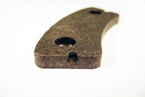
Organic linings are designed for use mostly on single engine aircraft and are made from a semi metallic mix combining brass, copper, iron, Kevlar a high temperature phenolic compound. They are attached to the back plates and pressure plates of a brake assembly using rivets. For removal and installation, see below. Metallic linings are designed for heavier and faster aircraft that develop higher kinetic energy in the braking process. To handle the high temperatures and associated wear, metallic linings are made by fusing small metal particles to a steel carrier plate in a process called sintering. Metallic linings are held in place on the back plates and pressure plates of a brake assembly by mounting pins that engage recesses in the back of the lining. Once the brake assembly is bolted together the linings are locked in place. For removal and installation, see below.
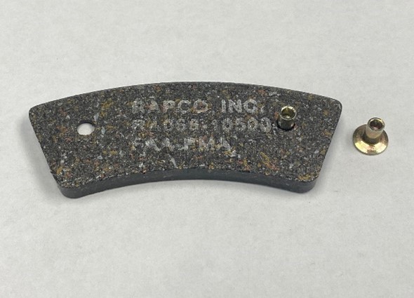
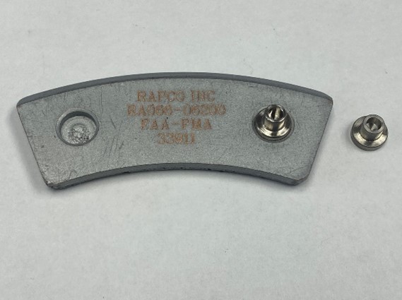
| Organic Lining with Rivet | Metallic Lining with Mounting Pin |
How are Organic or Metallic linings removed or installed?
Refer to your Aircraft Maintenance Manual for approved instructions. Also see section below on Brake Rivets & Mounting Pins.
When two different Linings PN’s are required on the same brake assembly, which goes where?
In the case of the Britten Norman BN2-Series, Dasher TB-30, Grumman American GA-7, Piper PA-24-400, PA-30, and PA-39 with the 30-23 brake assembly, two different brake lining part numbers are required. It is important that the linings are installed in the correct position. The RA066-06500 linings should be mounted on the pressure plate side near the piston, and the RA066-6200 linings should be mounted on the back plate that bolts onto the cylinder. This is shown in the RAPCO Application Guide as RA066-06500 (PP) for Pressure Plate and RA066-06200 (BP) for Back Plate.
How do I break in new brake linings?
Please click on link for RAPCO Inc. Service Letter RASL-004 PDF on brake lining and disc break in procedures.
What is the difference between the Cessna 208 Caravan standard and upgraded brake linings?
The RAPCO PN: RA066-15300 long life Brake Linings provides 30% more life for Cessna 208, 208B Caravans. They are 0.035 thicker and go on the 30-182A brake assembly. We will continue to offer the RA066-03300 standard lining for the 30-182 assembly. They both take the same RA177-00300 Mounting Pins. We also offer the RA068-02800 Shim Insulator and also produce the RA164-22201 Brake Disc.
BRAKE RIVETS & MOUNTING PINS
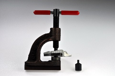
How do I use the RAPCO rivet tool?
See below or download Rivet Tool Instructions PDF
The RAPCO RA825 rivet tool is designed for use with tubular brass rivets in the installation of organic brake linings. For ease of operation, the base of the tool is designed to be clamped in a vise.
Removal of old rivets.
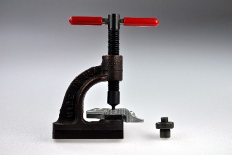
- Place the punch on bottom of the screw making sure the anvil is removed from the base of the tool.
- Position brake back plate or pressure plate in tool with lining on bottom and align rivet with punch. Turn the T handle clockwise to screw punch downward, pushing out old rivet. The rivets can also be carefully drilled out using an 1/8-inch (3.17 mm) diameter bit.
Installation of new rivets.
- Before installing new rivets, inspect and clean the back plates and pressure plates. Inspect the mounting surfaces to make sure they are clean and flat. Also be certain that the rivet holes are not worn or have developed a lip of metal around them. This can cause cracking of the linings or a squealing sound.
- Make sure that the punch is removed from the screw to expose the flaring tool machined into the tip of the screw.
- Place the large diameter of the anvil into the hole in the base of the tool.
- Insert the rivet into the large hole on the front side of lining and then through the hole in the flat side of the back plate or pressure plate.
- Hold the lining and plate with the rivet head on the bottom, then place the rivet head onto the anvil.
- Turn the T handle of the screw to allow the flaring tip to center on the rivet.
- Continue tightening the T handle to flare the rivet.
- To determine when the rivet is properly seated continue applying pressure to T handle while slightly rotating the plate assembly with lining from side to side. When it starts to become difficult to rotate it is properly seated.
Can a brake rivet have any splits in the flare?
Use of the RAPCO PN: RA825 Rivet Tool will help to reduce the chance or splitting the flared end of a rivet, however if it does happen only the following situations are approved.
- Splitting may occur only outside the crown of the flared rivet.
- A maximum of two splits within 90° of each other.
- A total of 3 splits per rivet.
How are metallic linings removed or installed?
Refer to the Aircraft Maintenance Manual for proper instructions. When the brake assembly is disassembled, metallic linings can be removed from the mounting pins by placing a screwdriver behind them and popping them off. After they are removed, wire brush the pressure plates and backplates. Inspect the pressure plates and backplates for any warping, cracks, or damage. Also inspect the mounting pins and make sure they are clean and have not become loose, worn, or damaged. If they need to be replaced, carefully drill out the old mounting pin with an 1/8-inch (3.17 mm) diameter bit and select the proper part number for replacement. Install the new pin using an impact set and anvil in an arbor press. The linings are simply placed on or lightly tapped in place and held on by friction. If the linings do not stay in place during reassembly, a light adhesive can be used on the back of the linings.
What tool do I use to install mounting pins?
The Installation of stainless-steel mounting pins can be accomplished using a rivet set and anvil in an arbor press. Refer to your Aircraft Maintenance Manual.
What rivet tool do I use when replacing wear pads on Cleveland heavy brake assemblies?
Please refer to your Cleveland Component Maintenance Manual for a specific brake assembly.
BRAKE SHIM INSULATORS
Why is it important to replace shim insulators?
Aircraft that use metallic brake linings generate a great deal of heat in the braking process. Shim insulators are necessary in these aircraft to reduce the transfer of heat from the lining to the brake cylinder. Without them the brake fluid can boil, causing the brake pedal to go to the floor. This can result in loss of control of the aircraft. The excess heat can also damage the O-rings. For these reasons, one should not make replacement shims out of aluminum or any other unapproved material. It is important to use only approved shims insulators made from proper material to critical specifications. Crushed shim insulators can cause uneven wear and shorten lining life as well. Always replace shim insulators when installing new linings or discs, or anytime they become damaged or worn. Replace as directed in your Aircraft Maintenance Manual.
DE-ICE BRUSHES and WIRE HARNESSES for Propeller
What causes a modular brush holder to become melted to the carbon brush?
If a carbon de-ice brush becomes melted to its insolated housing it is usually due to the following causes.
The terminals are touching each other due to a missing nylon spacer on one of the terminals. De-ice Module Drawings PDF
The brush is not properly aligned to the center of the slip ring. De-ice Brush Module minimum wear and alignment Information PDF under Support then Informational Tips on the RAPCO Inc. website.)
The wires are not properly connected causing is a short circuit in the system. Be sure to test each of the circuits separately.
Lightning strikes have also been known to have melted brush blocks.
EXHAUST GASKETS
What is the proper way to install exhaust gaskets?
Solid, Flat or Beaded Gaskets
Check the Aircraft Maintenance Manual for proper installation and torque spec. Make sure cylinder exhaust flanges and exhaust stack flanges are flat and parallel, or erosion can occur. In most cases solid gaskets should be installed in pairs with raised beads interlocked and facing away from the cylinder. In other words the raised bead should contact the exhaust stack flange. Re-torque exhaust nuts after a hot run.
Spiral Wound, Blo-Proof or No-Blow Gaskets
Check the Aircraft Maintenance Manual for proper installation and torque spec. Make sure cylinder and exhaust stack flanges are flat and parallel. Also check maintenance manual for exhaust nut torque spec. It does not matter which side of the exhaust gasket is mounted against the cylinder. Re-torque exhaust nuts after a hot run.
Can exhaust gaskets be reused?
It is not recommended to reuse neither flat nor spiral wound exhaust gaskets. They are designed to crush into place to fill the contours between each particular cylinder and the exhaust stack flange. A tight seal is necessary to block high temperature exhaust gases from eroding any uneven mating surfaces. If reused, old gaskets may not seal properly causing leaks and possible damage cylinders or exhaust stack flanges.
FUEL PUMPS
What causes premature failure of fuel pumps?
Fuel pumps that are only required to be operated for specific phases of ground or flight, will suffer a reduced service life when left on in continuous operation.
Another problem is Foreign Object Debris (FOD). It can be the result of contaminants such as sand or other debris entering the fuel system. It can also come from deterioration of components within the system such as Teflon tape, particles of rubber hose or fuel bladders that deteriorate and travel through the system causing damage to the pump.
Fuel pumps can also be damaged if they have not been properly primed at the time of installation or if they have been run dry at any point in their life.
Please be sure the following steps have been accomplished prior to operating your new or overhauled fuel pump.
- Force flushing multi-bay wet wing fuel tank systems.
- Thorough internal inspection of each of the fuel tank bays
- Removal of accumulated water and debris.
- Check all lines for dry rot and damage.
- DO NOT RUN DRY - Prime upon installation and never run pump dry.
- DO NOT use Teflon tape or sealant of any kind
- DO NOT open or disassemble pump at any time.
What does the NV mean in some of the Dukes fuel pump part numbers?
All current OEM Dukes Fuel Pumps for Beech aircraft have NV in the part number. The NV was added to the end of the part number to indicate compliance with the Dukes Service Bulletin that required the replacement of the old style pumps with carbon vanes. RAPCO or Fleet Support Services Dukes Fuel Pumps, all come with Nylatron vanes and have a yellow sticker that notes: This Pump Contains Nylatron Vanes, Do Not Run Dry, Replacement Vanes Must Be Nylatron.
What does the RX mean at the end of some of the Dukes fuel pump part numbers for Cessna?
The RX on the end of the Dukes fuel pump part number indicates that at some point it was a factory Remanufactured Exchange (RX) unit.
What is the difference between the Dukes fuel pump part numbers 4140-00-17 and 4140-00-17N ?
The N suffix signifies that the pump was designed specifically for installation in Navion H model aircraft with an STC for IO-520-B or IO-520-BA Engines.
DRY AIR PUMPS & PNEUMATICS
Why does my Dry Air Pump rattle when I hold it in my hand and shake it?
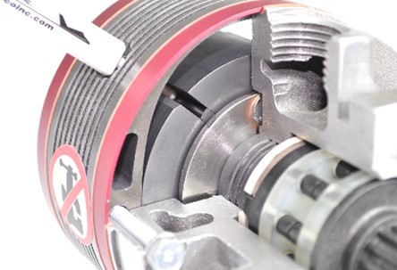
Dry air pumps have graphite carbon vanes that need to be able to slide in and out of the slots of the rotor to conform to the elliptical inside wall of the stator. During normal operation, the centrifugal force produced during rotation holds the vanes against the stator wall. This is what produces vacuum or pressure within the pump as it turns. When you shake the pump, you are hearing the vanes randomly sliding in and out of the vane slots. It is perfectly normal to hear this rattling sound.
Why can I not turn my Dry Air Pump drive spline with my fingers, while holding it in my hand?
You should be able to turn small 200 Series Dry Air Pump drive splines by hand, however if you have a 240 Series, or a 400 Series you most likely will not be able to do so. This is due to the fact that the that the larger pumps have a spring-loaded pressure plate that helps them to maintain higher output at altitude. The pressure plate creates friction which makes it much harder to turn, using your fingers.
How do I check the vane wear in my RAPCO brand pumps?
For instructions please refer to RAPCO Inc. Service letter RASL-006 PDF
What is the replacement time or hours in service for a dry air pump?
For dry air pump replacement times and hours first consult your Aircraft Maintenance Manual. If it is not published there, the original equipment manufacturer, Parker Airborne, required mandatory replacement at 500 hours or 6 years from date of manufacture, whichever comes first. For your specific RAPCO Inc. new or overhauled Airborne Dry Air Pump see RAPCO Inc. Service Letters Page.
Why does the lifespan of a dry air pump seem to differ from one aircraft to another?
The main factor in dry air pump life is the ratio of the accessory drive on a specific aircraft engine model. The faster the pump turns the shorter its life will be due to the increased friction that is generated at higher RPM. Operating temperature is another variable. If the pump has an ample supply of air flowing over it to cool, it will last much longer than a pump that is packed tightly into an accessory area with little air flow. Heat from turbo chargers makes the problem even worse. Also see premature failure below.
What factors cause the premature failure of a dry air pump?
Dry air pump failures can often be attributed to the following causes. Contamination, restriction of air flow through the pneumatic system or lack of proper airflow over the outside of the pump.
Failure on startup or within a few hours after installation is usually the result of carbon debris in the system that was not fully cleaned out after the failure of the previous pump. When a pump fails, the suction in the pneumatic system acts as a vacuum chamber drawing small particles of carbon from the damaged rotor and vanes backwards into the system where it can become lodged. If the entire system is not disassembled and thoroughly cleaned these particles can break free and travel through the new pump causing it to fail. After a dry air pump failure, be sure to replace all filters, remove and clean out all fittings and hoses and lines.
Sometimes pieces of hose get shaved off and fall into the system while the hose is being reinstalled on the fittings. In the case of older hoses that have deteriorated, pieces can break loose and get sucked into the pump at any time. All hoses in the system should be replaced every six years. Never use Teflon tape or other sealants in a pneumatic system. Particles get squeezed out of the threads and end up entering the pump, causing it to fail.
Oil, hydraulic fluid, or solvent contamination is another leading cause of premature dry air pump failure. In some cases, you might notice a reduction of vacuum indicated on the suction gauge over a period from a few hours to a few months. The gauge might also tend to come alive at an increasingly higher RPM. Most commonly, the oil will come from a worn or damaged oil seal within the engine accessory pad of which the dry air pump mounts. It can also come from other oil or hydraulic leaks in the engine compartment. Sometimes it is visible and sometimes in occurs in the form of a mist. Solvents used in the washing of an engine can also seep into a dry air pump, contaminating it and causing it to fail. Be sure to thoroughly cover the pump before washdown and do not run the engine until it has completely dried.
In aircraft with pneumatic de-ice systems that seem to have short dry air pump life, the problem can stem from any of the reasons above, however it is often due to an obstruction in the pneumatic system. This exerts excessive load on the pump, causing cupping of the graphite carbon vanes and eventual destruction. Also due to lack of air flow through the pump, it can overheat causing the shear coupler to melt or break. An obstruction can be caused by a kinked hose or insect nests; however, the most common problem is typically the result of one or more malfunctioning components in the pneumatic system. Airborne has life limited many of these components to 10 years. Often it is the de-ice control valve or dual stage regulator which sticks in a partially closed position causing obstruction of air flow. It is a problem that is difficult to discover because there is often enough air pressure to run the system, however there is not enough volume of air or flow to cool the pump properly. Airborne makes the 343 Test Kit, that may be helpful in diagnosing problems in the system.
Why am I getting shorter life out of my dry air pumps after installing a digital display?
If an electronic display has been installed and a gyro instrument has been removed, it is possible that there is no longer enough air flowing through the system to keep the dry air pump(s) from over temping. When one of the pneumatic lines are capped off, the regulator may be forced to operate outside of its design limits. Even if the suction or pressure gauge indicates the proper value as specified, there still might not be enough volume or flow (CFM) of air moving through the system to properly cool the dry air pump(s). Some have indicated that use of a vacuum restrictor valve in place of a capped off line has solved this problem for them. However, keep in mind that any air coming through the system should be filtered.
Can I buy a kit to overhaul my own dry air pump?
The first problem is that overhaul manuals are not available for dry air pumps and without an FAA approved process specification, the kits not legal for installation on type certificated aircraft. Also, the FAA does not consider it to be legal to overhaul a dry air pump other than within an FAA approved repair station with an approved test bench. In addition, if one were to buy a deluxe repair kit along with a stator and consider the cost of their time, they are close to the price of an FAA approved overhauled pump and they still do not have all the new parts that we put into our approved overhauls. If a pump is not built to specific tight tolerances it can fail to produce proper output or experience a very short life. Sometimes they will fail on startup. Without a warranty it can end up being very expensive, not to mention the safety aspect. RAPCO Inc. has never sold overhaul kits for dry air pumps and we do not recommend overhauling them on your own.
When do I need to install a 211CC-9 overhaul or RAP215CC-9 new dry air pump?
A dry air pump will run mounted in any position however both the 211CC-9 and RAP215CC-9 dry air pumps were specifically designed to be mounted vertically on the bottom of a Continental O-200 engine where they are more susceptible to oil contamination. If oil seeps into a dry air pump it will contaminate the graphite carbon dust and turn to sludge. This will eventually stop the vanes from moving freely and the pump will cease to produce suction. Oil contamination is the number 2 cause of premature dry air pump failure next to foreign object damage. Airborne attempted to deal with the oil contamination problem by putting a slinger ring on the drive shaft to throw off any oil that might drip down onto the pump. The oil is slung into a channel with a drain hole to try to get it away from the shaft. It helps, although if the oil problem is not soon resolved the pump will fail to operate. There were also a few other applications in which the aircraft manufacturer called out for the -9 pump to go on aircraft with Lycoming O-320 engines. Even though the pump is situated horizontally, it helped to reduce chance of oil contamination. On all RAPCO new dry air pumps we use a proprietary oil seal on the drive shaft instead of the slinger ring to help deal with oil contamination issues. In addition to the RAP215CC-9 all new RAPCO dry air pumps have it. The bottom line is, if your dry air pump mounts vertically, as in the case of a Continental O-200, or if it is specified in your aircraft parts manual, you will need to install the -9 pump.
What are the differences between new and overhauled exchange dry air pumps?
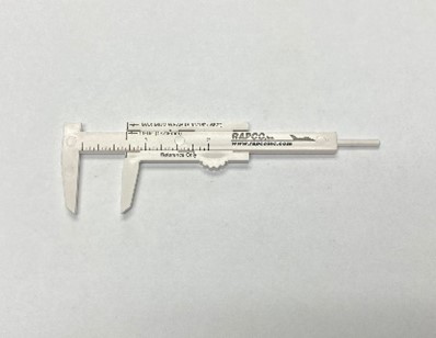
New RAPCO Inc. Dry Air Pumps are FAA-PMA approved as a direct replacement part. They come with an easy access inspection port and a caliper to help monitor the vane wear. In addition, new pumps have an oil seal on the drive shaft to help prevent damaging oil or solvents from entering the pump. New pumps also have longer warranty than overhauled pumps. Also, when purchasing a new dry air pump there is no core charge to pay or core to return, however if you wish to sell your old Airborne or RAPCO core, RAPCO will purchase it from you.
What is the difference between the 200 series, 240 series, and 400 series dry air pumps?
When purchasing a dry air pump for your specific aircraft be sure to refer to the Aircraft Parts Manual, Illustrated Parts Catalogue, Minimum Equipment List or Supplemental Documentation for the correct part number.
200 series dry air pumps are designed to run two pneumatic instruments in a vacuum or pressure system at lower altitudes. The 211CC and 212CW do not have cooling fins while the 215CC and 216CW do.
240 series dry air pumps are designed to maintain output at higher altitude, and they will run three pneumatic instruments or 2 instruments and a vacuum driven autopilot or an inflatable door seal, in a vacuum or pressure system. Check your Aircraft Parts Manual or Minimum Equipment List to see if a 240 series dry air pump is required.
400 series dry air pumps are designed to maintain output at higher altitudes. Each pump will run four pneumatic instruments, or two instruments, de-ice equipment or cabin door seals, in a straight or a combination of vacuum and pressure systems.
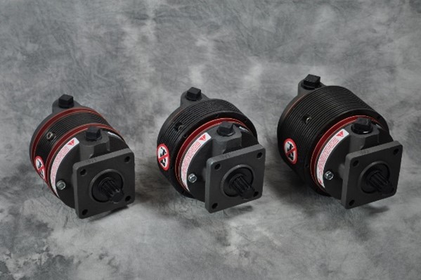
RAPCO Inc. Dry air Pumps: 200 Series, 240 Series, & 400 Series
Does it matter in which direction I mount my pump?
Even though it is most common to mount a dry air pump with the ports on top, it can be mounted in any position necessary. Keep in mind that it is essential to have adequate airflow moving over the outside and through the inside of the pump to offer proper cooling or it will suffer a short life.
What is the torque spec for the mounting nuts on my dry air pumps?
Always first consult your Aircraft Maintenance Manual. If it is not published their, the original equipment manufacturer recommended that when installing a dry air pump to use a new gasket, then torque the mounting nuts evenly to 70-inch pounds.
SUCTION GAUGE
Why does my suction gauge change with altitude while remaining at the same RPM?
When the suction gauge changes at different altitudes while the engine RPM remains constant, the problem is usually a faulty regulator. It has malfunctioned and is no longer able to compensate for varying pressure altitudes. Replace the regulator. Keep in mind that the original equipment manufacturer and most Aircraft Maintenance Manuals require an inspection at 5 years and every year thereafter until 10 years, then replace the regulator at 10 years.
VACUUM REGULATORS
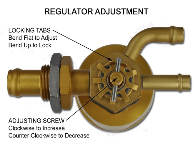
Can a vacuum regulator be adjusted?
RAPCO FAA-PMA Regulators come factory preset to a specific suction value for each part number. Each unit is put through a series of tests on a calibrated test bench to assure that it meets the required standards. If the regulator needs adjustment it may be due to other problems in the system.
If after installing a new regulator, or anytime the aircraft suction gauge reads outside of its normal operating range, first consult the Aircraft Maintenance Manual to confirm that all service instructions and Service Letters have been complied with. This includes replacing all pneumatic filters at least annually and all rubber hoses every six years. Also test or replace all necessary pneumatic components as specified. Valves, manifolds, and regulators should be tested at five years from date of manufacturer and then every year thereafter until ten years, replace at ten years. Dry air pumps should be replaced every six years. In some instances, suction will drop off towards the end of a pumps service life. Suction gauge calibration should be tested. Be aware that modifications to the system can result in problems. If all service instructions have been complied with and there is still a problem, check for leaks or malfunctioning components in the system. The Airborne 343 Test Kit can be helpful in doing so.
If you have completed the above and still feel that it is necessary to adjust the regulator be sure to do so in accordance with the following procedure: Push back the tabs on the bottom of the regulator that lock the T handle of the adjusting screw in place.
CAUTION: Turning the T handle of the regulator adjusting screw more than two (2) full turns in either direction can damage the regulator. If the adjusting screw is turned to the point of binding while turning it in (clockwise) or becomes disengaged while turning it out (counterclockwise) be aware that the warranty will be void. Make small adjustments of not more than one quarter (¼) turn at a time, turn the T handle clockwise to increase vacuum, or counterclockwise to decrease vacuum. Be sure to reset the lock tabs once you have finished.